SVCam Tools#
For FXO, EXO, HR, SHR cameras
All SVCam Assistant tools#
All SVCam Assistant tools enable you to deselect “Compatible only” and to list not compatible cameras. Moreover, you can deselect “Auto refresh” and click Refresh manually.
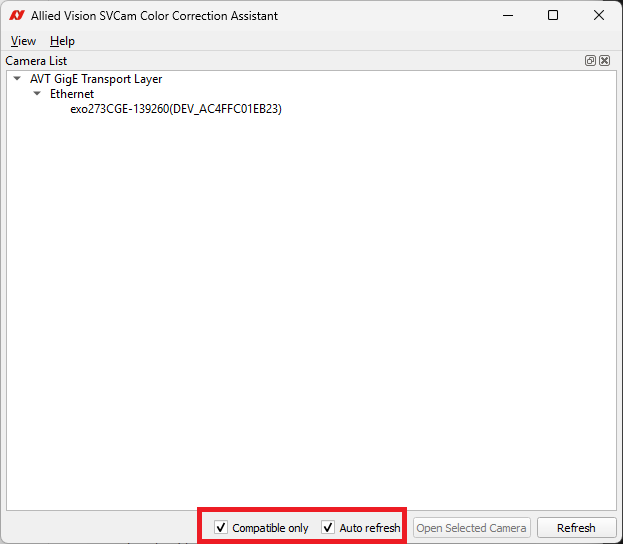
If a camera is listed as compatible but unsupported, your firmware version might be the reason. Contact us to get the latest firmware: https://www.alliedvision.com/en/company/contact-us/technical-support-and-repair-rma
SVCam Color Correction#
SVCam Color Correction helps you to generate a color correction matrix.
Preparation#
To prepare generating a color correction matrix:
Set up an illumination according to your use case.
Make sure that the camera uses a color pixel format. You can use Vimba X Viewer to change pixel formats.
Check if your camera supports Color Interpolation. If yes, select your desired method.
Use a color reference target (color checker), place it in front of your camera, and adjust the focus.
Generating a color correction matrix#
To generate a color correction matrix:
Start SVCam Color Correction Assistant and open your camera. By default, only compatible cameras are shown, and by default, the list refreshs automatically.
Click Import Live Image to acquire images of the color reference target. Adjust the exposure time if necessary. Alternatively, click the drop-down and select Import Local Images if recorded images are available. You can use Vimba X Viewer to save images, see Saving images
Define the AOI (Areas of Interest) with your mouse. Drag the mouse (top-left to bottom-right) to match the color fields of the color reference target.
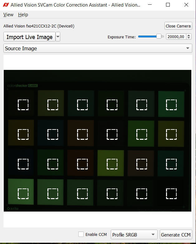
Select a profile, for example: Profile SRGB.
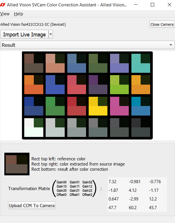
Click Generate CCM Matrix.
In the Result window, click Upload CCM To Camera.
SVCam Defect Pixel Correction#
Overview#
SVCam Defect Pixel Correction supports the following functionalities:
Analyze dark and bright images to detect defect pixels.
Generate a defect pixel map based on detected defect pixels.
Save, upload, and download defect pixel maps.
Display the number of defect pixels of the generated map.
Depending on the camera revision, SVCam Defect Pixel Correction supports the corresponding correction algorithms.
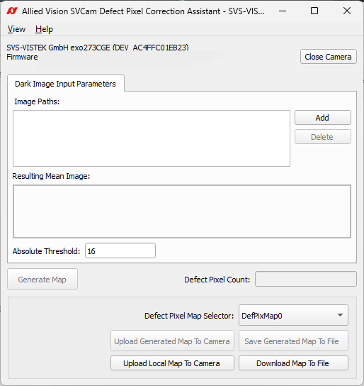
Image input requirements#
To generate a defect pixel map, SVCam Defect Pixel Correction uses two separate sets of images:
Dark images and bright images for monochrome cameras
Dark images for color cameras
Dark images#
Dark images are used to identify pixels that are permanently too bright (hot pixels).
To capture dark images, note the following:
Supported image format: 8-bit BMP (grayscale or color)
Make sure that no light reaches the sensor, use a lens cap.
Recommended number of images: 16 or more.
Bright images#
Bright images are used to identify pixels that are permanently too dark (dead pixels).
To capture bright images, note the following:
Image format: 8-bit BMP (grayscale or color); dark and bright images must have the same dimensions.
The scene must be uniformly illuminated.
Recommended number of images: 16 or more.
After adding new images to each set, the software calculates the mean image for a set. The mean images are then used internally for defect detection. The Defect Pixel Count is updated after each addition.
Camera revisions and correction algorithms#
The defect pixel map is generated for two camera revision types, each with a different correction algorithm.
Cameras with Revision 3:
Default revision.
Simple correction algorithm: defect pixels are replaced by their left neighbor.
Cameras with Revision 4:
Cameras with IMX990 and IMX991 sensors.
Enhanced correction algorithm with correction values derived from neighboring pixels and upper and lower rows.
Predefined settings from the file deffmatch.ini are used to match defect pixel types.
Defect Pixel Map Selector#
When the camera exposes the FileAccess interface (DefPixMap0 and
subsequent entries in the FileSelector feature), the
Defect Pixel Map Selector combo box is populated with the
available map slots (e.g. DefPixMap0, DefPixMap1, …).
When the camera does not expose the FileAccess interface, the combo box is populated from the DefectPixelCorrection_MapSelect GenICam feature instead, or from camera registers as a final fallback.
The selected slot determines the target of all upload and download operations.
Defect Pixel Map#
The map format depends on the camera’s FileAccess support:
Cameras with FileAccess (.bin)
Binary file.
The map is packaged as a GE3 container and transferred to the camera via the GenICam FileAccess interface.
Cameras without FileAccess (.txt)
Plain-text file.
Map structure:
One entry per line:
X; Y; TypeX: horizontal pixel position
Y: vertical pixel position
Type field:
Default value = 0 (Revision 3)
Revision 4: the type is determined by matching against predefined settings in deffmatch.ini
Typical usage workflow#
Capture dark images (lens cap on) and bright images (uniform illumination) and save them as BMP files.
Add the dark images on the Dark Image Input Parameters tab and optional for mono-cameras: the bright images on the Bright Image Input Parameters tab.
After the images are added, the mean images are calculated and the Defect Pixel Count is shown. You can adapt Absolute Threshold to your use case.
Click Generate Map.
Click Upload Generated Map To Camera or Save Generated Map To File.
After a successful upload, you will be prompted to save the map and the current camera settings to the active User Set so that the correction persists across power cycles.
SVCam NUC Correction#
Overview#
SVCam NUC Correction supports the following functionalities:
Analyze dark and bright images to measure fixed-pattern noise and pixel-to-pixel sensitivity variation.
Generate a per-pixel NUC (Non-Uniformity Correction) map.
Load, save, upload, and download NUC maps.
Upload correction maps to the camera for real-time non-uniformity correction.
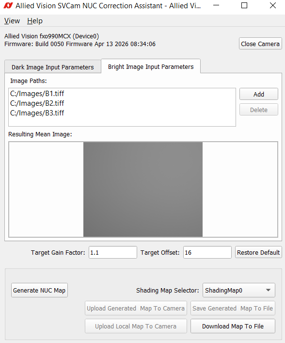
Image input requirements#
The assistant uses two separate sets of images: dark images and bright images. You can use Vimba X Viewer to create 16-bit TIFF images, see Saving images
Dark images
Captured with the lens cap on (no illumination). Dark images characterize fixed-pattern noise and the black level of the sensor.
Image format: 16-bit grayscale
Make sure the lens is fully covered. No light must reach the sensor.
Recommended number of images: 16 or more.
Bright images
Captured under uniform illumination. Bright images characterize pixel-to-pixel sensitivity variation across the sensor.
Image format: 16-bit grayscale; dark and bright images must share the same dimensions and bit depth.
Make sure the scene is uniformly illuminated (flat-field target or integrating sphere).
Recommended number of images: 16 or more.
After adding new images to each set, the assistant calculates the running mean image for this set. The mean images are then used internally for NUC map generation.
NUC correction parameters#
Two parameters control the correction map generation:
Target Gain Factor (default: 1.1)
This factor is applied to the bright reference images to define the target brightness the camera should achieve under uniform illumination. Setting it slightly above 1.0 pushes the sensor close to saturation. The computed gain correction is then limited (clamped) to the range [1.0, 2.0].
Target Offset (default: 16)
This factor describes the desired mean pixel value in a dark scene (lens cap on). This corresponds to the target black level. The resulting offset correction is clamped to the range [0, 63].
Click Restore Default to reset both parameters to their default values.
Camera types#
SVCam NUC Correction supports two camera types with different upload mechanisms.
Standard cameras:
The NUC map is uploaded directly to the camera via register writes.
The map is stored as a binary file with the extension .bin.
DOPO cameras:
Cameras that expose the
NucControlGenICam feature.The NUC map is packaged as a GE3 container file (.ge3) and uploaded to the camera’s user file storage via the GenICam FileAccess interface.
Up to five map slots are available:
nuc_usermap0.ge3throughnuc_usermap4.ge3.The target slot is selected from the Target User Map File Name dropdown, which is only visible for DOPO cameras.
NUC Map#
The NUC map encodes one dark offset value and one bright gain value per pixel, packed into a 16-bit word:
Bits [15:10] — dark offset (6 bits, range 0–63)
Bits [9:0] — bright gain (10 bits, range 0–1023, representing gain values in [1.0, 2.0])
Standard cameras (.bin)
Binary file structure:
Bytes 0–3: image width (32-bit unsigned integer)
Bytes 4–7: image height (32-bit unsigned integer)
Remaining bytes: interleaved float pairs (dark, bright) for each pixel, in row-major order
Standard cameras with FileAccess (.bin)
When the camera exposes the File Access interface (shading map entries in the File Selector feature), the GE3 container and the corresponding chunk structure are added as a header to the binary file structure according to the camera type.
DOPO cameras (.ge3)
GE3 container file with two chunks:
DOPO chunk: camera metadata (exposure time, temperature, gain, bit depth, black level)
NUC992_1 chunk: image width, height, and the packed 16-bit map data
Typical usage workflow#
Capture dark images (lens cap on) and bright images (uniform illumination) and save them as PNG or BMP files.
Add the dark images on the Dark Image Input Parameters tab and the bright images on the Bright Image Input Parameters tab.
After the images are added, the mean images are calculated and displayed.
For DOPO cameras, select the target map slot from the Target User Map File Name dropdown.
Adjust Target Gain Factor and Target Offset if needed, or click Restore Default to use the defaults.
Click Generate NUC Map.
Click Upload Generated Map To Camera or Save Generated Map To File.
Select the TARGET User Map file name to be uploaded or downloaded.
Standard cameras without Shading Map correction through File Access: After a successful upload, you will be prompted to save the map and the current camera settings to the active User Set so that the correction persists across power cycles.
SVCam Shading Correction#
Overview#
SVCam Shading Correction supports the following functionalities:
Analyze bright images to measure pixel-to-pixel sensitivity variation (vignetting).
Generate a shading correction map based on 16×16 pixel cluster analysis.
Load, save, upload, and download shading correction maps.
Select the target shading map slot on the camera.
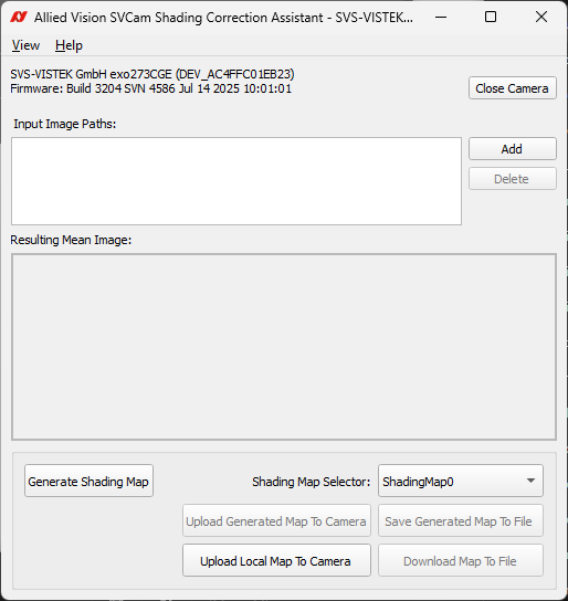
Image input requirements#
The assistant uses multiple bright images to characterize the spatial sensitivity of the sensor.
Image format:
16-bit grayscale
8-bit grayscale or color BMP
The scene must be uniformly illuminated (flat-field target or integrating sphere). Avoid specular reflections and dust.
All images in a session must have the same dimensions and bit depth.
Recommended number of images: 16 or more bright images.
You can use Vimba X Viewer to create 16-bit TIFF images, see Saving images
After adding new images, the assistant calculates the mean image from the available image set. The mean image is then used internally for cluster analysis and map generation.
Camera revisions and correction algorithms#
SVCam Shading Correction supports several camera revision types, each with a different cluster extraction method.
Revision 0: Default value.
Default revision.
Standard 16×16 cluster extraction: the image is divided into a grid of 16×16 pixel blocks. The mean brightness of each block is used as the cluster value.
Cameras with Revision ≠ 0:
Cameras with non-standard tap boundaries (tap-aligned sensor readout).
Tap-offset-aware cluster extraction: block positions are shifted by an offset derived from the camera’s tap size registers, so cluster boundaries align with tap boundaries in the sensor.
For both revisions, the correction coefficient for each cluster is computed by normalizing against the brightest cluster in the image (coefficient 1.0). All other clusters receive a coefficient greater than 1.0, which amplifies their output to match the brightest region.
Shading Correction Map#
The shading correction map is a plain-text file with the extension .txt.
Map structure for cameras without File Access:
Line 1: image width and height, separated by
;Remaining lines: one correction coefficient per line, in row-major order (left to right, top to bottom), followed by
;Coefficient values are floating-point numbers ≥ 1.0
Example (4×2 image, 8 cluster values):
4; 2;
1.12;
1.08;
1.03;
1.00;
1.15;
1.10;
1.05;
1.02;
Cameras with File Access (.bin):
Binary file
The map is packaged as a GE3 container and transferred to the camera via the GenICam FileAccess interface.
Typical usage workflow#
Capture bright images under uniform illumination and save them as PNG or BMP files.
Add the images to SVCam Shading Correction.
After the images are added, the mean image is calculated and displayed.
Select the target map slot from the Shading Map Selector dropdown.
Click Generate Map.
Click Upload Generated Map To Camera or Save Generated Map To File.
After a successful upload, you will be prompted to save the map and the current camera settings to the active User Set so that the correction persists across power cycles.
SVCam File Access#
Overview#
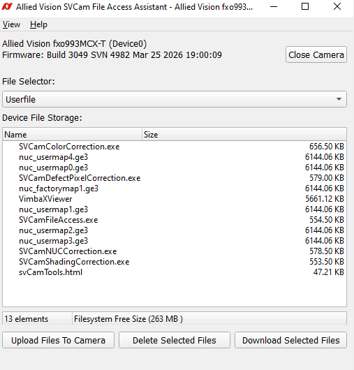
SVCam File Access supports the following functionalities:
List files stored on the camera.
Upload files from the local computer to the camera.
Download files from the camera to the local computer.
Delete files from the camera.
Upgrade camera firmware.
File Selector#
Cameras with SD card
For cameras equipped with an SD card the File Selector dropdown determines which category of files on the camera is currently active. All upload, download, and delete operations apply to the selected category.
Typical categories:
UserFile — user-managed files in the camera’s file storage. Multiple files can be listed, uploaded, and downloaded simultaneously.
Firmware — camera firmware image. When this selector is active, the UI switches to firmware upgrade mode (see Firmware Upgrade below).
Additional selectors may be available depending on the camera model.
The device file storage panel lists the files present in the selected category, showing their names and sizes. Available free space on the camera storage is also displayed.
Cameras without SD card For cameras without SD-card, the File Selector represents the list of available file selector slots, which can be used for file operations (download, upload). The file storage panel and the button Delete are not available.
Uploading Files to the camera#
To upload files to the camera:
Select the target file category from the File Selector dropdown.
Click Upload Files To Camera.
Select one or more files in the file dialog.
A progress bar tracks the transfer. All buttons are disabled until the operation completes.
The file dialog reopens in the last-used directory on subsequent uploads.
Downloading Files from the camera#
To download files from the camera:
Select the file category from the File Selector dropdown.
Select one or more files in the device file storage list.
Click Download Selected Files.
Choose a destination folder. If a file with the same name already exists, you will be prompted to replace it, skip it, or cancel.
A progress bar tracks the transfer.
Alternatively, right-click a file and choose Save As… to save it to a specific location.
Deleting Files from the camera#
To delete files from the camera:
Select the file category from the File Selector dropdown.
Select one or more files in the device file storage list.
Click Delete Selected Files.
Confirm the deletion in the dialog that appears.
The file list updates automatically after deletion.
Firmware Upgrade#
Warning
Do not reset the camera manually! First, make sure that the camera can be rediscovered and reopened. If the firmware is still outdated after the update, the reset may not be complete successfully. In some cases, the camera may need to be reset again for the changes to take effect.
To upgrade the camera firmware:
Go to the File Selector dropdown and select Firmware. The user interface switches to firmware upgrade mode: the file list and standard file operation buttons are hidden and Upload Firmware appears.
Click Upload Firmware.
Select the firmware file (
*.ge3) in the file dialog.The transfer starts. A progress bar tracks the upload. The firmware upgrade may take more than one minute.
When the upload is complete, the camera resets automatically to apply the new firmware.
Typical usage workflow#
Connect a camera and open it. The File Access Assistant panel becomes enabled.
Select the desired file category from the File Selector dropdown.
View the files listed in the device file storage panel.
Perform the desired operation:
To upload: click Upload Files To Camera and select files.
To download: select files in the list and click Download Selected Files.
To delete: select files in the list and click Delete Selected Files and confirm.
To upgrade firmware: select Firmware from the File Selector, click Upload Firmware, and select the
.ge3file.